Graphics Pipeline
In the previous 8 chapters on WebGL, we have covered many concepts and have also worked hands-on with code.
Now, finally, it’s the right time to understand the foundation of all graphics: the Graphics Pipeline.
Some of you might be wondering why we are talking about the foundation in the 9th chapter. That might feel a bit unusual, right?
Most books introduce the graphics pipeline right at the beginning—and I did study it at the very start as well. However, I couldn’t fully understand it back then. In my experience, having a basic understanding of shaders is essential before the graphics pipeline really starts to make sense.
Let's start by understanding the stages involved in the graphics pipeline:
Stages of the Graphics Pipeline
The graphics pipeline starts after the vertex data has been prepared and copied from system RAM to GPU memory (VRAM), and a draw call is issued.
Broadly, there are six stages in the graphics pipeline.
- Vertex Shader Stage
- Primitive Assembly Stage
- Rasterization Stage
- Fragment Shader Stage
- Per-Fragment Operations Stage
- Framebuffer Stage
To understand each stage, we will use an example of drawing two triangles
using 6 vertices: [P0, P1, P2, P3, P4, P5].
Let’s look at each one in detail.
1. Vertex Shader Stage
The graphics pipeline begins with the execution of the vertex shader.
When a draw call is made, its last argument tells the GPU how many vertices it needs to process. The vertex shader then runs once per vertex, and all invocations happen in parallel.
Let’s understand this using our example of drawing two triangles.
We have 6 vertex coordinates stored in a buffer, and we issue the following draw call:
gl.drawArrays(gl.TRIANGLES, 0, 6);
For the above draw call the vertex shader runs 6 times once for each coordinate in parallel and for each coordinate it sets the value of gl_Position.
Do not think that the gl_Position is a kind of global variable, its different for each vertex.
The figure below will help you understand this stage better:
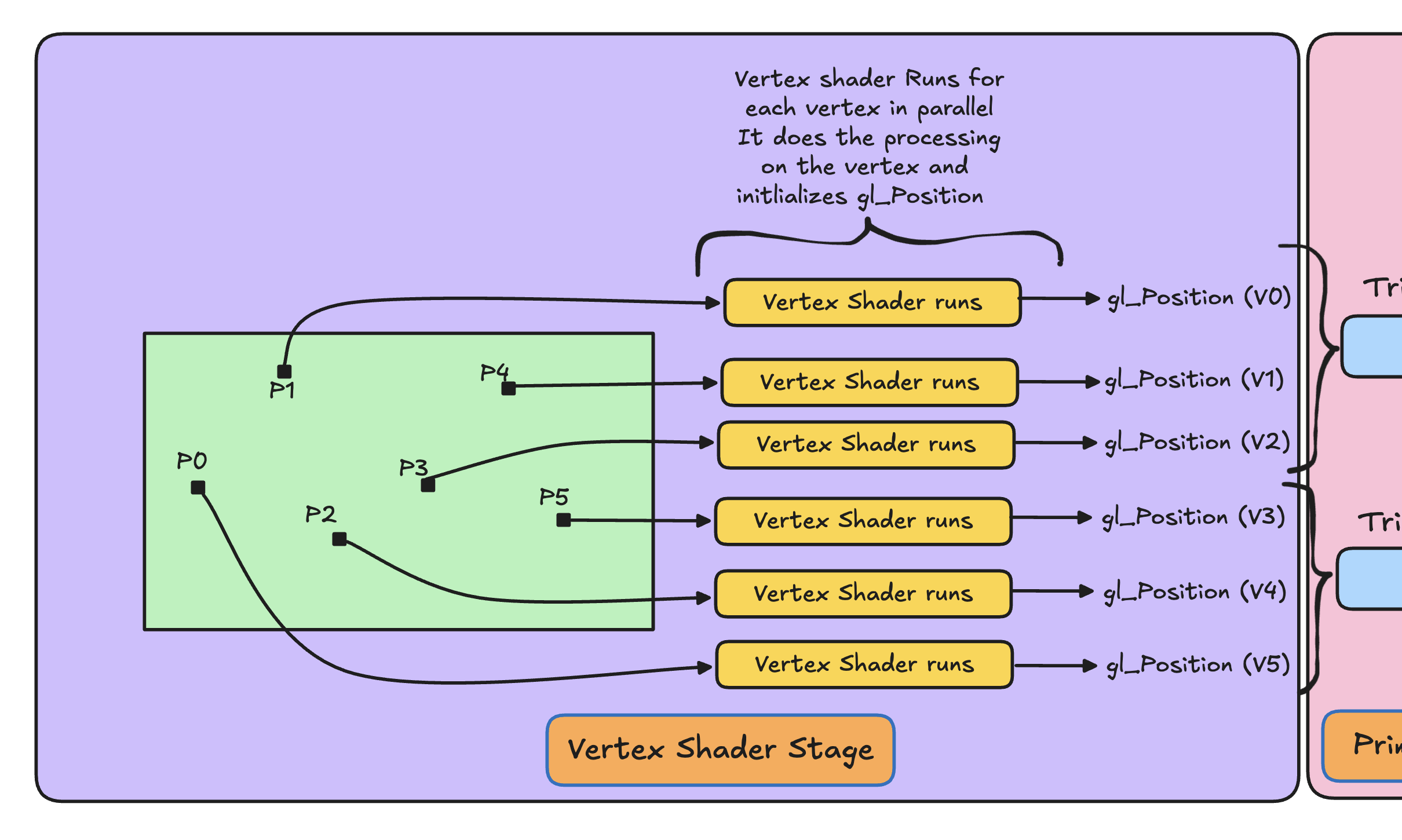
The vertex shader stage does not depend on the primitive you are drawing it just depends on the starting vertex and the number of vertices you want to draw.
All the transformations such as rotation, scaling etc. on the input points P0, P1, ..., P5 happen in this stage in the vertex shader. The final transformed position of each vertex is written to the built-in variable gl_Position.
We will refer to the outputs of the vertex shader stage as V0, V1, ..., V5, and these are passed to the next stage that is the Primitive Assembly Stage.
3. Primitive Assembly Stage
Let’s understand this stage in a conversational way.
After the Vertex Shader Stage, the GPU knows what are the vertices that will be used to draw.
Now the GPU asks, “What is it that we need to draw?”
The answer comes from the first argument of gl.drawArrays which says "Draw triangles, my lord!".
Now the GPU knows that the vertices should be interpreted as triangles.
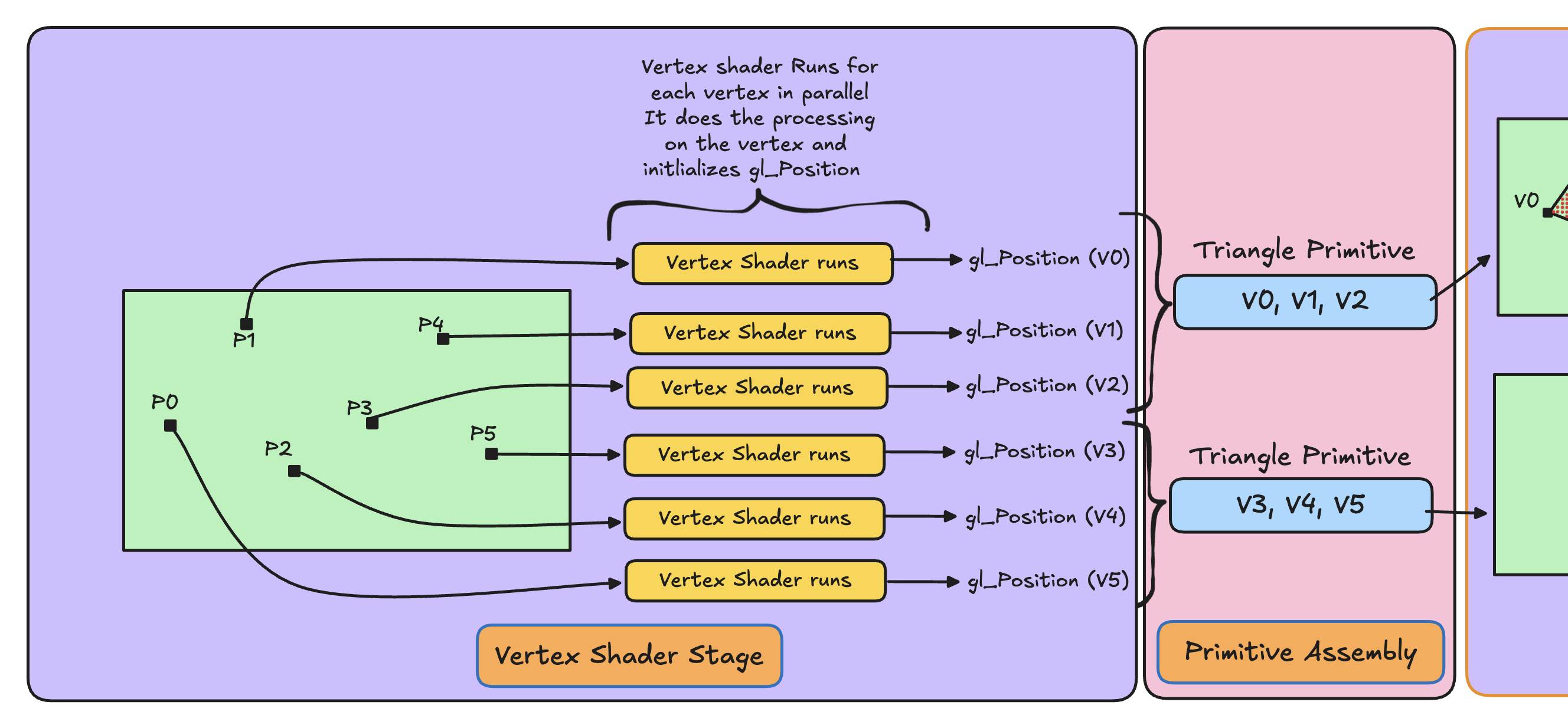
Then the GPU thinks: “One triangle requires 3 vertices. If I have 6 vertices, V0, V1, ..., V5, I can draw 2 triangles.”
Now in the Primitive Assembly Stage GPU forms the following triangle primitives:
- Triangle 1 →
V0, V1, V2 - Triangle 2 →
V3, V4, V5
These assembled primitives (vertices interpreted as triangles) are then passed to the next stage, which is the Rasterization Stage.
Here is the illustration for this stage, where the blue boxes show the primitives formed:
4. Rasterization Stage
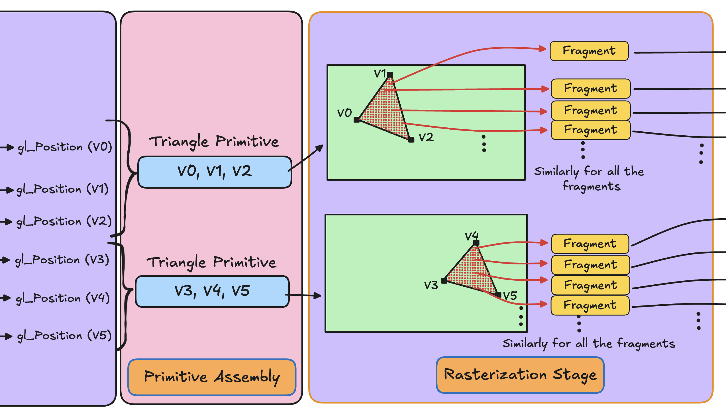
Rasterization is the process of determining which screen pixels are covered by a primitive and generating fragments for those pixels.
In the chapter GPU and Shaders, fragments were described as the pixels inside a primitive that are to be painted. However, that was a simplification. In reality, a fragment is not a pixel.
A fragment is a digital representation of a pixel that stores information like the position on the screen of that pixel, it's depth value, and interpolated data from the vertex shader. In this sense, a fragment is similar to an object in OOP: it represents an entity and holds its data, but it is not the final entity itself.
The rasterization stage takes in the primitives generated by the primitive assembly stage and determines what all pixels lie inside the primitive and then generates fragments for those.
So you can say that the rasterization stage generates a bunch of fragments which can be assumed to be like objects representing pixels, storing data like pixel position, depth etc.
This stage also performs interpolation of the outputs produced by the vertex shader across the primitive. We will explore this in detail later while building the RGB Triangle.
5. Fragment Shader Stage
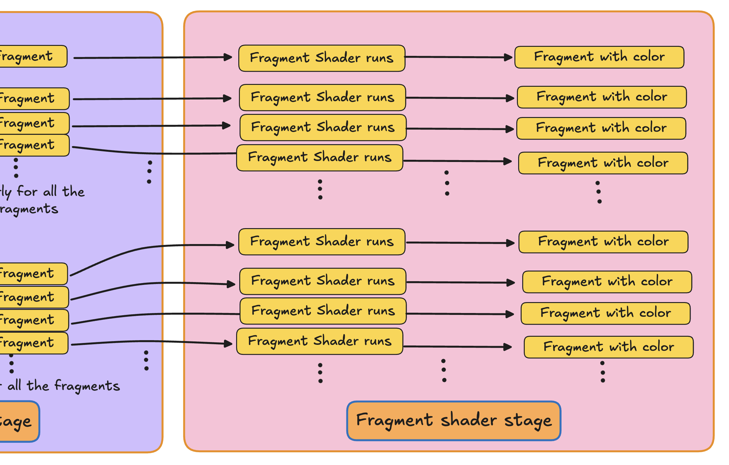
The fragments generated by the Rasterization stage are received by the fragment shader stage.
In the fragment shader stage, all these fragments are processed by passing them through the fragment shader. The fragment shader runs once for each fragment and outputs a color value for that fragment.
Let's see a illustration to understand better:
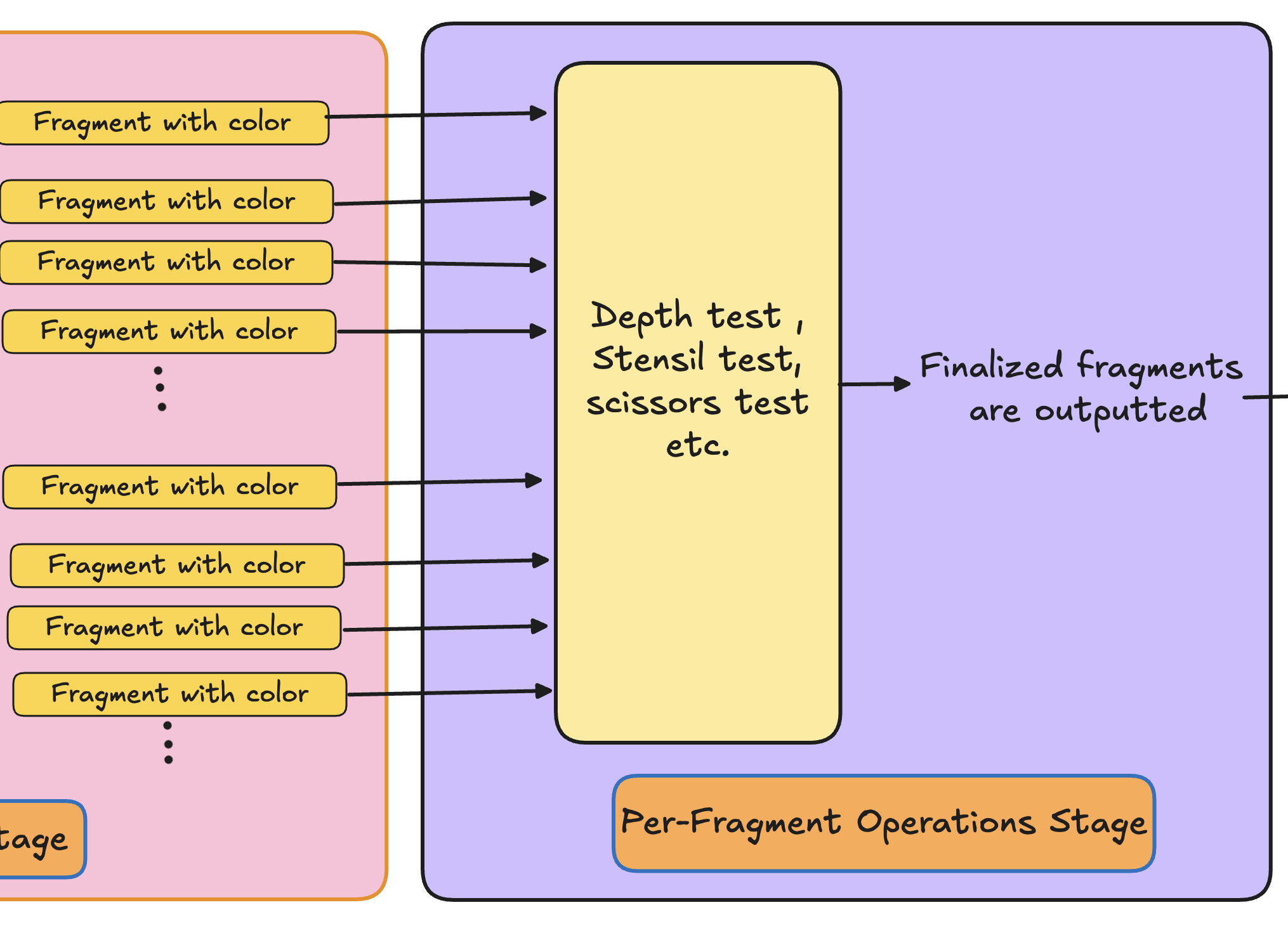
6. Per-Fragment Operations Stage
You could write the color of each pixel directly to the framebuffer right after the fragment shader stage and display it. However, since WebGL works with 3D scenes, this introduces an important nuance.
Imagine two triangles in a 3D scene, one placed behind the other. The question then arises: which triangle should be visible on the screen, and which one should be hidden?
Here's where this Per-fragment operations stage comes to our rescue.
In this stage all kinds of tests like depth test, stencil test, scissors test etc are done. Fragments which fail any of these test are discarded, and final fragments that are ready to be written to the frame buffer and displayed are outputted.
We will see these tests and how are they performed internally in later chapters.
Let's see the illustration:
7. Framebuffer Stage
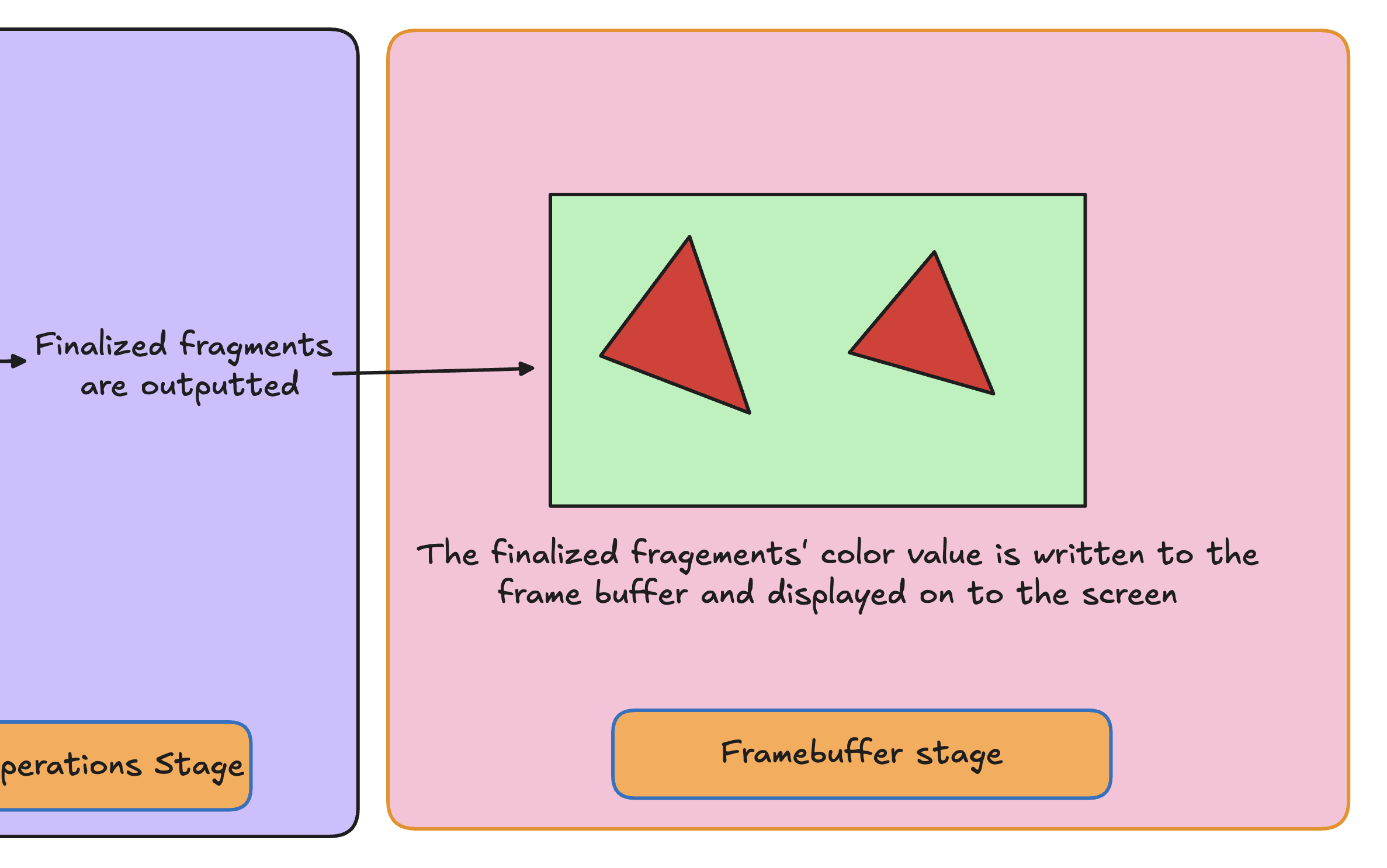
The fragments that pass all per-fragment operations are written to the framebuffer. This typically includes writing the final color to the color buffer, and updating the depth and stencil buffers if they are enabled. The contents of the framebuffer are then ready to be displayed on the screen.
Let's see the illustration of the framebuffer stage:
Let's see a full picture of all the stages of graphics pipeline:
